Scanners for medium format film are typically orders of magnitude more expensive than their 35mm eqivalents yet often still do not offer the same kind of resolution. This article describes a reliable method to use almost any 35mm scanner for medium format work.. To be more precise the scanner should have an APS feeder although other models might work too. Basically, an adapter is used to scan 24mmx36mm large portions of medium format transparencies. The pieces are later assembled together using stitching software, eg my free Photoshop plug-in Panorama Tools or PTStitcher. Any length can be scanned: The same holder works for 6x4.5/ 6x6/ 6x7 /6x9 etc. The process is quite lengthy and cumbersome, and not useable for large volume work, but the results are excellent and worth the effort in special cases.
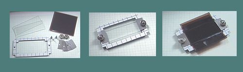
Adapter for MF transparencies
The adapter has to position a selectable portion of the transparency at the correct position in the scanner. The main problem is to achieve film flatness which is solved in the current approach by sandwiching the film between two glasses (microscopy glas). This ensures perfect flatness, actually better than what is achieved in 35mm film using the original holder or slides. The glasses are gently pressed together and select a 24mmx60mm stripe. This can be scanned in two runs by inserting the holder either way in the scanner.
The right figure above shows the adapter selecting the
middle stripe of a 6x6 transparency which is then inserted into the scanner.
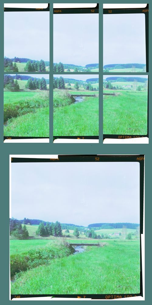
For 6x6 transparencies I need to scan 3 stripes, which adds up to 6 partial
images. We can scan any rollfilm based format that way, eg 6x4.5 (4 images)
or 6x9 (8-10 images). For the images to fit together the scanner has to
be set to constant exposure for each image.
Joining the Images
This is the most tedious part since the images need to be adjusted individually. While horizontal and vertical translation is easily accomplished, there is always some additional rotational mismatch to correct, which is more difficult to handle. The following methods work:
Manual Adjustment in Photoshop
We have to create a new canvas the size of the final image, and load each scanned image into a separate layer. Then we adjust each pair of images. Making one of the two images of each pair 50% transparent aids in judging the fit. The measurement tool can be used to determine and correct the rotational error. We repeat these steps for each pair of images. Then we crop each image at appropriate seem positions, apply the feather tool, and flatten the whole image.
This approach gives a reasonable fit and with some practice is quite fast. However, sometimes the pieces just don't fit perfectly, especially if scanned at higher resolutions. This is due to very slight changes of film position in the scanner, which results in different magnifications. The differences are typically smaller than 0.2%, which can be as much as 5 pixels. This can be visible in critical images, and is corrected in the next method.
Semiautomatic adjustment using Panorama Tools
Panorama Tools's position optimizer can be used to determine optimum shift and rotation parameters for each image. It also determines optimum magnification factors to correct misalignments. We have to provide at least two feature points for every pair of overlapping images, and then run the position optimizer in the submenu 'adjust' of Panorama Tools. This creates a scriptfile which can be used to merge the images either using 'Panorama Tools' again, or PTStitcher. The following is a step-by-step explanation of this process.
(1) Creating a script file
See the example script which
we can reuse for any image, which is scanned at 1360dpi. It contains a
line of text discribing the final image (starting with the letter 'p')
and one line for each input image (starting with 'i'). We have to insert
width and height appropriate for our images depending on the resolution
of the scanner. We choose format and field of view as specified in the
example, even if our particular lens has other properties. These values
ensure that Panorama Tools simply joins the images and does not apply any
perspective corrections as it usually does. For these reasons, yaw, roll
and pitch corrections should all be set to 0 (y0
r0 p0). Field of view in the p-line has to be larger than in the i-line
by the ratio of transparency width (6cm in this case) to scanned image
width (24mm). Finally, we have to supply the horizontal(d)
and vertical(e) pixel-distance of each scanned image relative to the center
of the MF-image. We can use this scriptfile for all our images.
(2) Selecting feature points
We number the images from 0 to 5, and select pixel coordinates
for each pair of overlapping images. Then we enter coordinates according
to the syntax described in the eample script. We can either read out feature
points automatically using the flags image provided in the Panorama tools
documentation, or read coordinates using Photoshop's info palette.
(3) Optimizing Positions: We enter a list of parameters to be optimized (see line starting with 'v'), then select 'adjust' in Panorama Tools, click 'Run Optimizer' and 'Browse' for the script. Clicking 'ok' runs the optimizer and adds commands for Panorama Tools to adjust the images. We can check the scriptfile, which has now information about how close the feature points could be merged.
(4) Merging the Images in Panorama Tools, or PTStitcher, which is simpler: We select all images (which should be numbered in the order they appear in the script) and the scriptfile, and drop them all onto PTStitchers icon. Weare asked for the resultfile location, and then all images are merged. If our script specified Photoshop file format, we will get a multilayer image file containing one image per layer, which we can flatten if we are satisfied with the fit.
There are many more options available in PTStitcher like
seam positioning and output formats, see the separate tutorials available
at my site. Also notice that despite the many
correction steps required for joining the images, there is actually only
one resampling step involved. This sampling step uses a bicubic or better
interpolator thus preserving the quality of the original images.
1999 © Helmut Dersch der@fh-furtwangen.de