Correcting Barrel Distortion
Helmut Dersch
(der@fh-furtwangen.de)
Technical University Furtwangen
Updated July 14th 1999
The following examples demonstrate the use of my Photoshop/Gimp
plug-in Panorama Tools
to correct lens distortions. The most common and annoying lens error is
barrel distortion, which occurs in many cheap wide angle lenses, especially
in digital cameras or when using wide angle adapters. Straight lines are
bent away from the center of the image: A rectangle looks like a barrel.
Correction of these distortions is performed by shifting each pixel radially.
The displacement is calculated using a polynomial function, whose coefficients
are specific to the particular lens. Once these coefficients have been
determined, they can be reused for each image: In practice the images should
be batch-converted to correct these errors. Panorama Tools employs a high-quality
sampling algorithm with negligible image degradation, so no new errors
are introduced during this process.
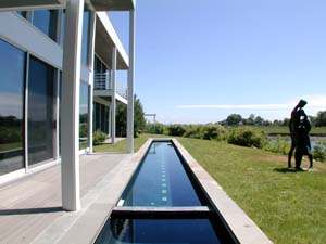
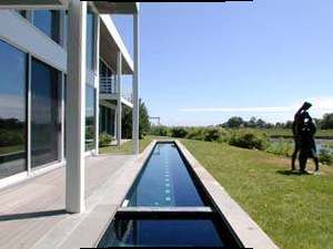
The following examples (left image) shows an image made
with the Nikon Coolpix 950 using the wide angle lens (24mm equivalent,
image courtasy Barry Hyman). In architectural images like this one, barrel
distortions are particular noticeable. The corrected image to the right
shows straight lines as we are used to.
To perform these corrections you need an installation
of Panorama Tools. Open your image, select 'Panorama Tools' and 'Correct'.
Click 'Radial Shift' and enter these options: a=0; b=0; c=-0.075; d=1.1.
Use the same values for all colors. Please note that the correct values
may be different for your lens, even if you also have the Nikon CoolPix.
They were determined using the tiny images above, and should
be refined on larger images.
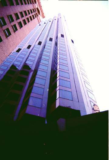
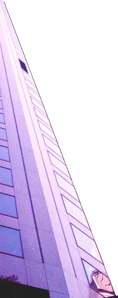
The next example shows a scanned image made with a Zoom
lens and 35mm equipment (Vivitar 28-80mm, Olympus OM1). These lenses often
exhibit barrel distortions in the wide angle settings, although it usually
is significantly smaller than in the example above. Still, it can be quite
annoying when making enlargements. To show the effect on the screen, I
have enlarged a part (right edge of the building) and inserted a straight
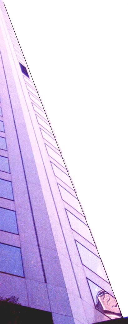
line. Clearly, a slight curvature can be observed. (Left image below).
If you can't see it on the screen (it is scaled down inside the browser),
I recommend to download it and display it in a graphic viewer. The right
image is an enlargement of the corrected image, using the parameters: a=0;b=0;c=-0.02;d=1.02.
The correction always has to be performed on the entire image. Correcting
just a portion does not work.
How to determine suitable Parameters:
The correcting function is a third order polynomial. It
relates the distance of a pixel from the center of the source image (rsrc)
to the corresponding distance in the corrected image (rdest)
:
rsrc = ( a * rdest3
+ b * rdest2 + c * rdest + d ) * rdest
The parameter d describes the linear scaling of the image.
Using d=1, and a=b=c=0 leaves the image as it is. Choosing other d-values
scales the image by that amount. a,b and c distort the image. Using negative
values shifts distant points away from the center. This counteracts barrel
distortion, and is the basis for the above corrections. Using positive
values shifts distant points towards the center. This counteracts pincussion
distortions. Correcting using 'a' affects only the outermost pixels of
the image, while 'b' correction is more uniform.
Finally, you may correct pincussion and barrel distortions in the same
image: If the outer regions exhibit barrel distortions, and the inner parts
pincussion, you should use negative 'a' and positive 'b' values. If you
do not want to scale the image, you should set d so that a +b + c + d =
1.
In most cases, you will get quite satisfactory results
by using just one parameter, like the 'b'-parameter in the above examples.
These examples may also serve as a guide to how large these values should
be, ie around 0.1 if the distortion is quite visible, or around 0.01 if
it is very small. Simply optimize this starting value until you like your
image.
Some additional Notes:
-
The internal unit used for rsrc and rdest
is the smaller of the two image lengths divided by 2. In the case
of portrait orientation, this is the width, in the case of landscape orientation
it is the height. That means rsrc = 1 is the top or right edge
of the image. This has the advantage that the same parameters a,b,c,d can
be used to correct scans made with different resolution. You can also use
the same parameters a,b,c,d for landscape and portrait orientation.
This is different in older versions of Panorama Tools (1.8b2 and older),
which always normalized to the width of the image. If you have determined
Parameters for this older versions, you need to either use the portrait
values from now on for all images, or calculate the portrait values from
the landscape parameters using these formulas for 35mm equipment
(36mm*24mm):
-
aportrait = alandscape * (24/36)3
-
bportrait = blandscape * (24/36)2
-
cportrait = clandscape * 24/36
-
dportrait = dlandscape
-
In Photogrammetry, similar but not identical parameters k1
and k2 are used. If you happen to know these values for your
lens, you can convert them using the width (portrait mode, else height)
of your image (in mm) and these formulas:
-
a = k2 * (width/2)3
-
b = 0
-
c = k1* (width/2)
-
d = 1
-
The above procedure assumes that the optical axis coincides
with the center of the image. This is usually not exactly the case, either
due to misalignement of the lens, or due to scanning errors. You can shift
the image vertically and horizontally using the 'Vertical Shift' and 'Horizontal
Shift' options. These transformations can be performed in one step together
with the radial shift.
-
The radial shift tool allows you to enter different parameters
for each color. This feature enables you to correct color errors which
are quite common in ultra wide and fisheye optics. If you notice color
seams at the edges of your image, these are usually due to uncorrected
dispersion of the front element, which can be corrected by shifting the
rgb-color channels against each other.
-
If you use Photoshop as plug-in host, you should consider
converting the images to Lab-color space prior to correction. Interpolation
of colors works best in this color mode.
-
Shift/Tilt correction of the images can be performed at the
same time using the 'adjust' tool. See the separate tutorial
about this feature.
-
You can get more accurate results for a,b,c,d by either calibrating
your lens using a test chart, or by using Panorama Tools' built-in optimizer.
See the documentation 'HowToAlign' in the distribution.
Copyright ©; H. Dersch 1999